Author: Paul B. Anders
Date: 8/14/02
Version: 2.4
This table is my "best effort" at sorting out all of the variations of D-Jetronic injection parts for the various years and models of the 1.7L and 2.0L engines. I cannot say with 100% certainty that the table below is accurate, and I found several conflicts for the listed parts among the various Bosch and Porsche documentation that I used to compile the table. Use the table at your own risk. I assume no responsibility for problems encountered as a use of the information presented here.
References (and acronym used in the table below):
|
|
"Bosch Gasoline and Diesel Injection Products", (BGDIP) from Bosch. 1998 revision. Available from Bosch. |
|
|
"Bosch Ignition Parts", (BIP) from Bosch. 1997 revision. Available from Bosch. |
|
|
"914 Porsche Technical Specifications Guide", (PTS) from Porsche, 5/1/1974. No longer available. |
|
|
"D-Jetronic Service Manual", (DSM) from Bosch, no date. Available at: http://www.boschservice.com/http-docs/access/kjetron.htm |
|
|
"Porsche Parts Catalog 914 and 914-6", (PPC) from Porsche, 1/1995. No longer available (NLA). Copies are seen on Ebay from time to time, and there is the "PIC" CDROM catalog that also shows up on Ebay. |
|
|
"Porsche 914 / 914-6 Factory Workshop Manuals", (FWM) from Porsche, revised 11/17/1981. Available at: http://www.pelicanparts.com/catalog/shopcart/9144/POR_9144_documt_pg1.htm#item2 . Microfiche of these manuals are also seen on Ebay. |
|
|
"Troubleshooting Guide for Engines with Electronic Fuel Injection MPC (manifold pressure controlled)", (VWTG) Volkswagenwerk AG, http://www.seanster.com/vw/VW%20MPC%20Troubleshooting%20Guide.zip (NOTE: very large 12 MB zip file of JPG images) |
|
|
"Kaesedorf Gemischbildung Vol IV" (Kaesedorf Air/Fuel Mixture Volume IV) Data on injector flow rates from this book, from Roland Kunz on Pelican Parts BBS |
914 D-Jetronic Engine Codes (there is a good reference at: http://www.dgi.net/914/tech/technical.html ):
| Engine Code | Displacement | Region | Number Range |
| W | 1.7L | World | 1970: 0 000 001
to 0 057 460 1971: 0 057 461 to 0 129 581 1972: 0 129 582 to 0 250 000 |
| EA | 1.7L | World | 1972: 0 000 001
to 0 057 000 1973: 0 057 001 to 0 098 793 |
| EB | 1.7L | USA | 1973: 0 000 001 to 0 009 703 |
| GA | 2.0L | USA | 1973: 0 000 001
to 0 006 765 1974: 0 006 766 to 0 015 021 |
| GB | 2.0L | non-USA | 0 000 001 to ?? |
| GC | 2.0L | USA | 1975: 0 000 001
to 0 002 914 1976: 0 002 915 to 0 006 946 |
| Part | Porsche/VW # | Bosch # | Engine | Year | Notes |
| ECU | 022 906 021 022 906 021 U |
0 280 000 007,
008 CU89X |
1.7L | 1970 ? | Discrepancies:
The BGDIP lists the
CU89X for the 1970 914 1.7L, with 0 280 000 007 and 008 as Bosch
cross-references. It also lists the CU89X as being cross-referenced to VW
part number 022 906 021U. The PTS and FWM both list a 022 906 021 ECU for "August
1969" through "August 1970" - but the BGDIP cross-references this VW number to the CU47X, which is for the 1975 Type
2's. Characteristics: Unknown |
| 022 906 021 B 022 906 021 BU 022 906 021 BX |
0 280 000 015 CU11X |
1.7L | 1970 - 1971 | W0 000 001 => W0 129 581 The PPC specifies this ECU addition to the ECU above for 1970 1.7L's. Characteristics: Has over-run shut-off circuit, no idle mixture adjustment knob, five waveform generators in the speed control circuit |
|
| 022 906 021 A
& E 022 906 021 AU 022 906 021 EU |
0 280 000 037,
013, 038 CU13X |
1.7L 2.0L |
1972 - 1973 1973 |
W0 129 582 =>
W0 250 000 EA0 000 001=> EA0 098 793 EB0 000 001 => EB0 009 703 GA0 000 001 => GA0 006 765 GB0 000 001 => GB0 007 401 (AA web) Note: Use only the CU13X or the 022 906 021 E (Bosch 0 280 000 037) ECU with the 1973 2.0L engine. Characteristics: No over-run shut-off circuit, idle mixture adjustment knob present, five waveform generators in the speed control circuit. |
|
| 039 906 021 | 0 280 000 043,
044 CU14X |
2.0L | 1974 | GA0 006 766
=> GA0 015 021 Characteristics: No over-run shut-off circuit, idle mixture adjustment knob present, five waveform generators in the speed control circuit. |
|
| 039 906 021 A 039 906 021 AU |
0 280 000 051,
052 CU16X |
2.0L | 1975 - 1976 | GC0 000 001
=> GC0 006 946 Characteristics: Has over-run shut-off circuit, idle mixture adjustment knob present, four waveform generators in the speed control circuit. |
|
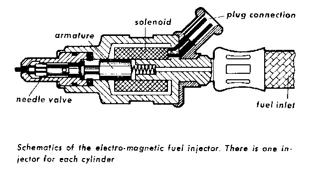
| Injection Valve | 022 906 031 A or 311 133 261 A |
0 280 150 009 | 1.7L | 1970 - 1976 | Yellow plug |
| 039 906 031 | 0 280 150 019 | 2.0L | 1973 - 1974 | Green plug | |
| 039 906 031 A | 0 280 150 038 | 2.0L | 1975 - 1976 | Green plug | |
| Injection Valve Seal | 311 133 263 311 133 261 |
1 280 206 702 1 280 206 703 |
1.7L, 2.0L | 1970 -1976 | One each required per injector. |
| Fuel Filter | 311 133 511 D | 0 450 901 003 | 1.7L, 2.0L | 1971 - 1974 | |
| 133 133 511 | 0 450 901 005 | 1.7L, 2.0L | 1975 - 1976 | ||
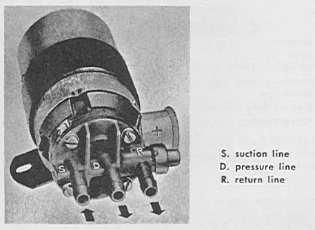
| Fuel Pump | 311 906 091 D | 0 580 463 005 | 1.7L, 2.0L | 1970 - 1974 | |
| 043 906 091 | 0 580 463 016 | 1.7L, 2.0L | 1975 -1976 | ||
| Auxiliary Air Regulator | 022 906 045 | 0 280 140 007 | 1.7L, 2.0L | 1970 - 1976 | No longer available. BGDIP also lists a 0 280 140 101 for the 74-75 914, and a 0 280 141 011 for the 1.7L 1970 to 1973. |
| Cold Start Valve | 022 906 171 A | 0 280 170 017 | 1.7L | 1970 - 1973 | |
| 311 906 171 B or PCG 906 171 B |
0 280 170 015 | 2.0L | 1973 - 1976 | ||
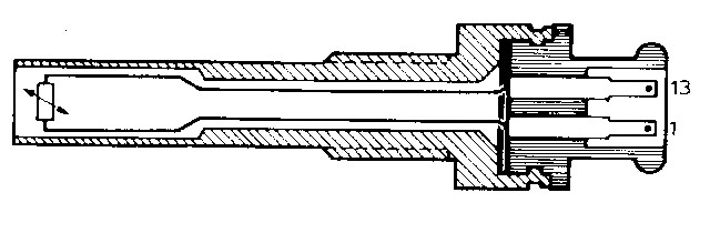
| Intake Air Temperature Sensor | 311 906 081 A | 0 280 130 006 | 1.7L, 2.0L | 1970 - 1976 | This part number was used on all versions of D-Jetronic (e.g. VW, Porsche, Volvo, etc.) |
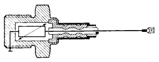
| Cylinder Head Temperature Sensor | 311 906 041 A | 0 280 130 003 0 280 130 012 |
1.7L 2.0L |
1970 - 1973 1974 - 1976 |
Discrepancies:
The PPC lists this Porsche/VW part number for the engines below.
The BGDIP cross-references this VW part number to the 0 280 130
003 sensor, which is the sensor for the 1968-1969 Type 3's. I checked with
my local Bosch supplier and the ...003 is the part he found for this
Porsche/WV number . The DSM lists the 0 280 130 012 sensor for these
engines and years, but not for the 1974 2.0L. Note that the 0 280 130 003 sensor is used by some 914
owners to get a richer cold engine mixture.
W0 000 001 => W0 250 000 |
| 022 906 041 | 0 280 130 012 | 1.7L | May 1971 Aug 1971 |
The PTS and the FWM list this part as the standard equipment. The 311 906 041 A is listed as the replacement part. | |
| 022 906 041 A | 0 280 130 017 | 2.0L | 1973 | Discrepancies:
The PTS, PPC, and FWM list this sensor only for the 1973's, but the DSM
lists it for both the 1973 and 1974's.
Used with the Ballast Resistor
below. The PTS and FWM list this sensor as a replacement for the 1.7L engines in cases of high fuel consumption. |
|
| Ballast Resistor | 039 971 762 A | N/A | 2.0L | 1973 | Non-Bosch, Wehrle part, 270 ohms. List price for this thing is nuts, >$20. Go to Radio Shack and buy a 1/4 or 1/2 watt resistor of near-equal value and a couple of crimp-on terminals for about $1 if you need this part. |
| Thermo Switch / Thermo-Time Switch | 311 906 161 A | 0 336 003 003 | 1.7L | 1970 | Thermo switch. From the PTS and
the FWM. Both state to only use this part with ECU 022 906 021
W0 000 001 => W0 057 460 |
| 311 906 161 C | 0 336 003 007 (BGDIP) 0 336 003 008 (actual) |
1.7L, 2.0L | 1970 - 1974 | Thermo
switch. BGDIP lists the Bosch number for this part as ending in 007.
Actual part (looked at two different parts) with this number is imprinted with Bosch number 0 336 003 008.
W0 057 461 => W0 250 000 |
|
| 022 906 163 A | 0 280 130 205 | 2.0L | 1975 - 1976 | From the PTS and
the FWM. GC0 000 001 => GC0 006 946 This is a thermo-time switch. It has an internal heater that limits the maximum time the switch will stay open under cranking, from 5 to 20 seconds, depending on the external temperature. |
|
| Deceleration Valve | 022 133 551 | 0 280 160 102 | 1.7L | 1972 - 1973 | 1970 -1971 1.7L 914's didn't have a decel valve, because their ECU cut off the fuel flow on overrun. |
| 039 133 551 | 0 280 160 108 | 2.0 L | 1973 - 1976 | ||
| Fuel Pressure Regulator | PCG 133 030 A | 0 280 160 001 | 1.7L, 2.0L | 1970 - 1976 | |
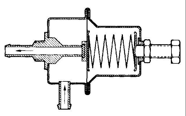
| Manifold Pressure Sensor | 039 906 051 | 0 280 100 043 | 2.0L | 1974 - 1976 | |
| 022 906 051 C | 0 280 100 037 | 2.0L | 1973 | GA0 000 001 => GA0 006 765 | |
| 022 906 051 E | 0 280 100 049 | 1.7L | 1970 - 1973 | ||
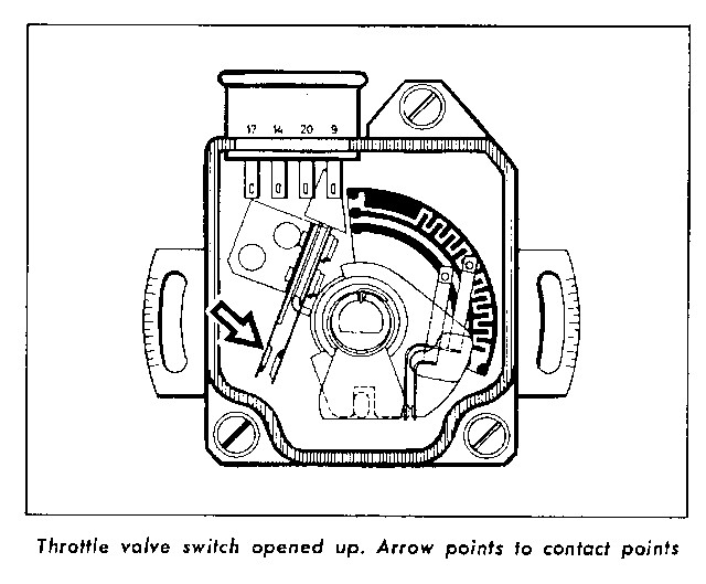
| Throttle Switch | 039 906 111 A | 0 280 120 032 | 2.0L | 1973 - 1976 | Note that the PTS and FWM list a 039 906 031 number for the 1973 2.0L switch - but that can't be correct, as that number is the same as the injector number. |
| 022 906 111 A | 0 280 120 042 | 1.7L | 1970 - 1971 | W0 000 001 => W0 129 581 | |
| 022 906 111 B | 0 280 120 021 | 1.7L | 1972 - 1973 | W0 129 582 =>
W0 250 000 EA0 000 001 => EA0 098 793 EB0 000 001 => EB0 009 703 |
|
| Main Relay | 311 906 061 | 0 332 003 021 | 1.7L | 1970 - 1973 | W0 129 582 => W0 250 000 |
| Trigger Contacts | 311 905 301 | 1 230 090 000 | 1.7L, 2.0L | 1970 - 1976 | |
| Distributor (vac unit listed where available) |
039 905 205 (diz) 022 905 271 C (vac) (vac from BIP) |
0 231 174 009
(dizzy) 1 237 122 601 (vac) (PIP & PP web) |
2.0L | 1973 | GA0 000 001
=> GA0 006 765 (PPC, FWM, and PTS) |
| 039 905 205 A (diz) 039 905 271 (vac) (vac from BIP) |
0 231 174 011
(dizzy) 1 237 122 603 (vac) (BIP & PP web) |
2.0L | 1974 - 1976 | GA0 006 766
=> GA0 015 021 (PPC, FWM, and PTS) |
|
| 039 905 205 B (diz) 039 905 271 (vac) (vac from BIP) |
0 231 172 021
(dizzy) 1 237 122 603 (vac) (BIP and PP web) |
2.0L | 1975 - 1976 | GC0 000 001
=> GC0 006946 PPC lists te vac as a 039 905 271 A instead. |
|
| 022 905 205 A | ?? | 1.7L | ?? | Graphs in FWM, no usage noted. Not in the BIP. | |
| 022 905 205 B | ?? | 1.7L | ?? | Graphs in FWM, no usage noted. Not in the BIP. | |
| 022 905 205 D (PTS & FWM) |
?? | 1.7L | 1970 | W0 000 001 =>
W0 007 333 (PTS & FWM)
No entry in the BIP for the 022 905 205D. |
|
| 022 905 205 E (PTS & FWM) |
0 231 172 007 (from Ralf H. on Rennlist - right off the dizzy) |
1.7L | 1970 | W0 007 334 =>
W0 039 125 (PTS & FWM)
No record of a ... 172 007 in the BIP. No Porsche or VW part number cross-referenced and no record of a ...205 E dizzy. But, this seems to be the actual part used on 1970 914's, two '70 1.7L owners have verified. |
|
| 022 905 205 F (diz) 022 905 271 A (vac) (PTD & PPC) |
0 231 174 001 (from a dizzy up on Ebay, and from the BIP for a '70) | 1.7L | 1970 | W0 039 126 => W0 057 460 (PTS & PPC)
Supposedly the same as E, with speed limiter rotor - however, comparison of part numbers stamped on an E and F distributors show significantly different Bosch numbers. No ... 205 F entry in the BIP for the Porsche or VW, but the BIP lists the 0 231 174 001 for the '70 1.7L. |
|
| 022 905 205 H (diz) 022 905 271 B (vac) (PPC) |
0 231 163 011 (BIP) |
1.7L | 1971 - 1972 | W0 057 461 =>
W0 250 000 (PPC)
BIP doesn't show this dizzy as used on any 1.7L engines, but it does show it as a VW dizzy for 1971 to 1972 Type 4's. |
|
| ?? | 0 231 174 005 | 1.7 L | 1973 | From BIP, "to 11/72". No Porsche or VW part number cross-referenced. | |
| ?? | 0 231 174 007 | 1.7 L | 1973 | From BIP, "from 11/72". No Porsche or VW part number cross-referenced. | |
| 022 905 205 P (diz) 022 905 271 C (vac) (PPC) |
0 231 172 019 (BIP) |
1.7L | 1970 - 1973 | W0 000 001 =>
W0 129 581 (PPC) EA0 000 001 => EA0 057 000 (PPC) EA0 057 001 => EA0 098 793 (PPC) EB0 000 001 => EB0 009 703 (PPC) BIP shows this dizzy as being for the 1973 Type 4. |
|
| 022 905 205 J | ?? | 1.7L | FWM (no description of the application), also listed in Automobile Atlanta web catalog. |
Distributor reference: Pelican Parts web site, PTS, FWM, and PPC. Accurate distributor part number matching is difficult for the 1.7L engines. The distributor data for the 2.0L models is reliable and consistent. Also included is info from http://www.dgi.net/914/tech/distrib.html . Be aware that 914 distributors are often referred to by only the last three numbers of the Bosch part number, such as "009" and "050". This can lead to confusion, as these two numbers usually are associated with mechanical-advance-only distributors used with carbureted engines (e.g "009" is really a 0 231 178 009). Since the 1973 2.0L distributor is number also ends in "009" (0 231 174 009), make sure the "009" you are looking at is a D-Jetronic model, which will have the vacuum unit and trigger contacts in the bottom of the unit. And to make it more confusing, the part number for the L-Jetronic 1974 1.8 L is 0 231 181 009!! So there are three 009's out there!
I also received some great information from Jeff Bowlsby (bowlsby@aol.com) on an often overlooked FI component - the wiring harness. Here are Jeff's inputs:
| Year |
Engine |
Displ | TPS | TS/TTS | Notes |
| 1970 | W | 1.7L | 4 pole | 1 pole | MPS mounted as in Haynes Fig 2.33 |
| 1971-72 | W | 1.7L | 4 pole | 1 pole | MPS rotated from Haynes Fig 2.33, otherwise same as W70 |
| 1972-73 | EA | 1.7L | 5 pole | 1 pole | Identical to W71-72 except for 5 pole TPS |
| 1973 | EB | 1.7L | 5 pole | 1 pole | Identical to EA |
| 1973-74 | GA | 2.0L | 5 pole | 1 pole | Physically unique, but electrically identical to 1.7L harnesses |
| 1975-76 | GC | 2.0L | 5 pole | 2 pole | Similar to GA, but CSV circuit is modified, no speed limiter |
| 1975-76 | GC/SL | 2.0L | 5 pole | 2 pole | Similar to GA, but CSV circuit is modified, w/speed limiter |
| Terminal(s) | Component | Expected value |
| 1 and 13 | TS1 - air temp sensor | 300 ohms @ 68 deg. F |
| 3 and ground | Fuel injector - cylinder 1 | < 3.0 ohms |
| 4 and ground | Fuel injector - cylinder 4 | < 3.0 ohms |
| 5 and ground | Fuel injector - cylinder 2 | < 3.0 ohms |
| 6 and ground | Fuel injector - cylinder 3 | < 3.0 ohms |
| 7 and 15 | MPS primary coil | 90 ohms (check each lead and make sure there is no continuity to the MPS case) |
| 8 and 10 | MPS secondary coil | 350 ohms (check each lead and make sure there is no continuity to the MPS case) |
| 9 and ground | Accelerator Pump Contact Track #1 | 10 indications of continuity from fully closed to fully open throttle |
| 20 and ground | Accelerator Pump Contact Track #2 | 10 indications of continuity from fully closed to fully open throttle |
| 11 and ground | ECU ground circuit | Less than 0.5 ohms |
| 12 and 21 | Trigger contact switch #1 | Alternating continuity as the engine is cranked |
| 12 and 22 | Trigger contact switch #2 | Alternating continuity as the engine is cranked |
| 16, 24 and ground | ECU power source from main power relay on regulator plate | Turn key to the "on" position, read voltage, should be less than 1 V difference from voltage measured at battery terminals. |
| 17 and ground | TPS idle contact | Less than 0.5 ohms when the throttle is closed, infinity when the throttle is opened more than 2 degrees. |
| 18 and ground | Start signal from ignition switch | Turn key to "start" position, read voltage, should be greater than 12V. |
| 19 and relay plate terminal III (white plug, back left corner) | ECU control line for the fuel pump relay | Less than 0.5 ohms |
| 23 and ground | TS2 - CHT, cylinder head temperature sensor | > 2K ohms at 68 deg. F for all but 1973 2.0 L, > 1.2 K ohms for 1973 2.0L |
The suggestions below are based on my analysis of the parts listings above and my own experience with my 2.0L car. These suggestions are for stock or nearly-stock engines. Euro pistons are OK, and maybe a bit of head milling to increase compression. Bumping displacement to 2.1 or 2.2L will require increasing the fuel pressure, or adjusting the MPS (NOT recommended), or both. No non-stock cams, porting, or throttle body modifications, if so, you're on your own.
I suggest that you use the later 1974 parts below for your 1973 engine. The 1973 cars came with the 022 906 021 E version of the ECU. This ECU required a special head temperature sensor (0 280 130 017) and a ballast resistor, as well as a specially adjusted manifold pressure sensor (0 280 100 037). While this arrangement works, replacement parts are getting harder to come by (especially the ...017 head temp sensor and the ...037 pressure sensor). The 1974 parts are more readily available. I am currently using the 1973 2.0L distributor (0 231 174 009) instead of the 1974 distributor (0 231 174 011) on my car, and it is working fine. If possible, however, I would suggest using the 1974 distributor, as it has slightly different mechanical and vacuum advance/retard settings that are optimized for emissions and fuel economy.
If you can find it, I suggest using the 0 280 130 012 head temperature sensor, but I have found this part difficult to obtain. From what I can tell, the 0 280 130 003 sensor is nearly the same (it has a longer lead wire) and is readily available. I have recently acquired an ...012 sensor and will add my characterization data to this page when complete. See my notes in the table above about this sensor and the part numbers.
I have no experience with the 1975 -1976 2.0L's, and I suggest following the parts table above for these engines.
I've described the availability of the parts in the notes. No actual prices are listed as they vary frequently. I used the Pelican Parts catalog for most of my information, but there are many other sources of these parts. Only four parts are listed as no longer available or unknown availability, but the number of parts unavailable is likely to grow. I suggest acquiring a stock of these parts today, as future prices are likely to be high. I have found some good deals on Ebay, but I suggest using Ebay only for those who feel comfortable with on-line bidding.
| Part | Porsche/VW # | Bosch # | Engine | Year | Notes |
| ECU | 039 906 021 | 0 280 000 043,
044 CU14X |
2.0L | 1974 | Available rebuilt. Some units available new, at a very high price (~$1K). |
| Injection Valve | 039 906 031 | 0 280 150 019 | 2.0L | 1973 - 1974 | Green plug. Available new and rebuilt. General wisdom is to pay the $$ and get new parts instead of rebuilt. |
| Injection Valve Seal | 311 133 263 311 133 261 |
1 280 206 702 1 280 206 703 |
1.7L, 2.0L | 1970 -1976 | One each required per injector. Available new. |
| Fuel Filter | 311 133 511 D | 0 450 901 003 | 1.7L, 2.0L | 1971 - 1974 | Available new. |
| Fuel Pump | 311 906 091 D | 0 580 463 005 | 1.7L, 2.0L | 1970 - 1974 | Available new. |
| Auxiliary Air Regulator | 022 906 045 | 0 280 140 007 | 1.7L, 2.0L | 1970 - 1976 | No longer available. Used units are your best bet, try a local auto recycler. Automobile Atlanta sells rebuilt units, but they're expensive - rebuilt it yourself and save $$. |
| Cold Start Valve | 311 906 171 B or PCG 906 171 B |
0 280 170 015 | 2.0L | 1973 - 1976 | Available new, but these seem to be in short supply. |
| Intake Air Temperature Sensor | 311 906 081 A | 0 280 130 006 | 1.7L, 2.0L | 1970 - 1976 | No longer available. This sensor was used on nearly every D-Jetronic application. Check your local Volvo, Saab, or VW dealer. Try a local auto recycler if you cannot locate a new sensor. |
| Cylinder Head Temperature Sensor | 311 906 041 A | 0 280 130 003 0 280 130 012 |
1.7L 2.0L |
1970 - 1973 1974 - 1976 |
Available new. The ...012 sensor is in short supply. Either sensor should work OK. |
| Thermo Switch | 311 906 161 C | 0 336 003 007 | 1.7L, 2.0L | 1970 - 1974 | Available new. |
| Deceleration Valve | 039 133 551 | 0 280 160 108 | 2.0 L | 1973 -1976 | Availability unknown. Try your local auto recycler. |
| Fuel Pressure Regulator | PCG 133 030 A | 0 280 160 001 | 1.7L, 2.0L | 1970 - 1976 | Available new. |
| Manifold Pressure Sensor | 039 906 051 | 0 280 100 043 | 2.0L | 1974 - 1976 | Available new and rebuilt. New units are expensive (up to ~$1K). Rebuilt units may have different bellows and diaphragm than stock and have been reported to have different response than OEM. I am currently using a rebuilt unit with no problems. If your unit is missing the epoxy seal over the full-load stop plug and has been "adjusted", I suggest replacing the unit. |
| Throttle Switch | 039 906 111 A | 0 280 120 032 | 2.0L | 1973 - 1976 | Available new. |
| Trigger Contacts | 311 905 301 | 1 230 090 000 | 1.7L, 2.0L | 1970 - 1976 | Available new. |
| Distributor | 039 905 205 | 0 231 174 009 | 2.0L | 1973 | Available new and rebuilt. New units are expensive (~$900). Dirt-cheap rebuilt units (A1 Cardone) are available from Checker for $70, including core charge! This distributor will work with a 1974 setup. |
| 039 905 205 A | 0 231 174 011 | 2.0L | 1974 | Available new and rebuilt. New units are expensive (~$900). Dirt cheap rebuilt units (A1 Cardone) are available from Checker for $70, including core charge! This is the suggested distributor. |
This table is a work-in-process, I'll update it as I complete more characterizations of ECU / MPS combinations. The intent is to identify the compatibility of non-OEM combinations of ECU's and MPS's. OEM combinations are identified with an "OEM" prefix and are highlighted blue. Other possible MPS's and ECU's are highlighted in green or yellow for potential application (none are exactly the same), red if there is no other combination that will work.
| ECU / MPS Compatibility Table |
ECU (0 280 000 YYY) |
|||||
|
007 or 008 (CU89X) |
015 (CU11X) |
037 (CU13X) |
043/044 (CU14X) |
052 (CU16X) |
||
|
MPS |
037 | OEM '73 2.0L | ||||
| No other MPS's will work | ||||||
|
043/044 ECU's 015 ECU (lacks idle adjustment) |
||||||
| 043 | OEM '74 2.0L | OEM '75-'76 2.0L | ||||
| 049 MPS | 049 MPS | |||||
|
037 ECU's 015 ECU (lacks idle adjustment) |
No other ECU's will work | |||||
| 049 | OEM '70 1.7L | OEM '70-'71 1.7L | OEM '73 1.7L | |||
| ? | 043 MPS | 043 MPS | ||||
| ? |
037 or 043/044 ECU's |
043/044 ECU's 015 ECU (lacks idle adjustment) |
||||
The following table relates some engine performance problems to specific FI parts. Here are a few good URL's to other D-Jetronic diagnostic procedures (some are non-914 but have good information):
http://www.914fan.net/djet.html (excellent
info on testing the injectors and fuel system) (also try: http://mail.symuli.com/vw/Djet.html
)
http://persweb.direct.ca/aschwenk/djettest.pdf
(table from Bosch Service Manual of the diagnostic procedure)
http://www.icbm.org/erkson/ttt/engine/fuel_injection/d-jet.html
(non-Porsche D-Jet document)
http://www.vclassics.com/archive/efi.htm
(non-Porsche D-Jet document)
Note that this troubleshooting table is from the perspective of what problems can be caused by a specific component.
| Part | Description | ||||||||||||||||||||||||||||||||||||||||||
| ECU |
|
||||||||||||||||||||||||||||||||||||||||||
| Injection Valve |
|
||||||||||||||||||||||||||||||||||||||||||
| Fuel Filter |
|
||||||||||||||||||||||||||||||||||||||||||
| Fuel Pump |
|
||||||||||||||||||||||||||||||||||||||||||
| Auxiliary Air Regulator |
|
||||||||||||||||||||||||||||||||||||||||||
| Cold Start Valve and Thermo or Thermo-Time Switch |
|
||||||||||||||||||||||||||||||||||||||||||
| Intake Air Temperature Sensor |
|
||||||||||||||||||||||||||||||||||||||||||
| Cylinder Head Temperature Sensor |
|
||||||||||||||||||||||||||||||||||||||||||
| Ballast Resistor |
|
||||||||||||||||||||||||||||||||||||||||||
| Deceleration Valve |
|
||||||||||||||||||||||||||||||||||||||||||
| Fuel Pressure Regulator |
|
||||||||||||||||||||||||||||||||||||||||||
| Manifold Pressure Sensor |
|
||||||||||||||||||||||||||||||||||||||||||
| Throttle Switch |
|
||||||||||||||||||||||||||||||||||||||||||
| Main Relay |
|
||||||||||||||||||||||||||||||||||||||||||
| Trigger Contacts |
|
D-Jetronic cars often suffer from various drivability problems that are due to maladjustment or component wear. This table is an ongoing listing of specific drivability problems, with likely causes and solutions. Remember!!! Before using this table, you must assure that the basic mechanical condition and the ignition system of the engine are in perfect working order, and that you have all the right D-Jetronic parts, no vacuum leaks, and that all of the measurable parameters listed in the tables above are within operating limits.
| Symptom | Cause | Solution | ||||||||||||||||||
| Engine bogs from idle (poor idle to part-load transition) | Idle mixture too rich | Set the CO level to factory specs by using a quality gas analyzer. If a gas analyzer is not available, use the "trial-and-error" method of adjusting the ECU knob one click counter-clockwise at a time, re-adjust the air bleed screw to set the idle and repeat if necessary. | ||||||||||||||||||
| Idle drops down well below 1000 rpm after the car is fully warmed up | Idle mixture too rich | Set the CO level to factory specs by using a quality gas analyzer. If a gas analyzer is not available, use the "trial-and-error" method of adjusting the ECU knob one click counter-clockwise at a time, re-adjust the air bleed screw to set the idle and repeat if necessary. | ||||||||||||||||||
| Adjusting the air bleed screw has no effect on idle speed (possibly accompanied by light backfiring during overrun, especially when the engine is cold) | Idle mixture too lean | Set the CO level to factory specs by using a quality gas analyzer. If a gas analyzer is not available, use the "trial-and-error" method of adjusting the ECU knob one click clockwise at a time, re-adjust the air bleed screw to set the idle and repeat if necessary. | ||||||||||||||||||
| Idle mixture adjustment knob on ECU has no effect on idle speed or mixture | Throttle switch misadjusted | Adjust throttle switch. See throttle switch section above for more detail. | ||||||||||||||||||
| Engine "bucks" or jerks at steady part-load throttle settings | Throttle switch
contacts worn Dirty trigger contacts |
Replace throttle switch. See throttle switch section above for more detail. If condition persists after testing the throttle switch, it may be due to dirty trigger contact points. | ||||||||||||||||||
| After starting when the engine is cold, the idle doesn't come up while the Aux Air Regulator is open (Aux Air Regulator operation has been verified by checking for draw on intake hose). Idle performance is good once the car is warmed up. | Cold mixture is too lean. Cold resistance of the cylinder head temperature sensor is too low. | Can you guess that I've had this problem with my car? :-) This problem seems to get worse on older cars as the engine wears. There are a couple of solutions. You can "cherry pick" a cylinder head temperature sensor with the highest value you can find, or you can add ballast resistance to the sensor - however, this will affect your mixture across they whole operating range (not recommended). A potential fix is to use a dash-mounted switch to add a ballast resistance to the sensor when cold, then turn it off (shunt it) when hot. I'll update this if I ever find a solution I like!! | ||||||||||||||||||
| Idle oscillates and/or idle is too high and cannot be adjusted down to 1000 rpm with the air bleed screw |
|
Check the
following areas for a vacuum leak: 1. Intake runner-to-head gasket/spacer |
||||||||||||||||||
| "My car runs rich and I don't know why!!" |
|
The best list I have of possible reasons for a persistent rich running condition. Check them all. |
|
|
1.0 - 5/5/01 - Initial release, document uncontrolled up to 6/11/01 with additional content added periodically |
|
|
1.1 - 6/11/01 - Added new information on thermo switches to the troubleshooting section |
|
|
1.2 - 7/2/01 - Added new information about contact cleaners for the throttle switch |
|
|
1.3 - 7/3/01 - Added new information about 2.0L injector flow rates, including the reference from Roland Kunz, updated info on 1.7L 1970 distributors based on new data. |
|
|
1.4 - 7/20/01 - Minor edits based on information from the PPC. |
|
|
1.5 - 7/27/01 - Added information on nominal injector resistances and inductances, and nominal MPS resistances and inductances. |
|
|
1.6 - 10/26/01 - Added symptom/cause/solution drivability troubleshooting table |
|
|
1.7 - 1/15/02 - Started adding component photographs for identification |
|
|
1.8 - 2/11/02 - Minor edits and clarifications |
|
|
1.9 - 3/08/02 - Added more component diagrams and photos |
|
|
2.0 - 3/22/02 - Added ECU/MPS compatibility table |
|
|
2.1 - 3/23/02 - Added more TS2 data, some minor edits |
|
|
2.2 - 4/11/02 - Added ECU characteristic data, reformatted and updated ECU/MPS compatibility table |
|
|
2.3 - 4/22/02 - Added photo link to TPS accelerator track wear |
|
|
2.4 - 8/14/02 - Added troubleshooting entry on causes of a persistent rich condition |